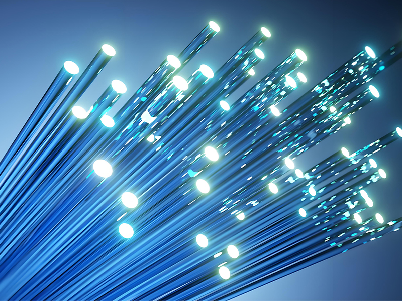
The field of fiber optic communication has revolutionized how information is transmitted across the globe. Since the first practical fiber optic system was deployed in the 1970s, this technology has become the backbone of modern telecommunications, enabling the internet, cable television, and high-speed data networks that we rely on daily.Optical fiber.Optical Transceiver.
A fiber optic communication system transmits information as light pulses through a glass or plastic fiber. Compared to traditional copper wires, fiber optic cables offer numerous advantages, including higher bandwidth, longer transmission distances, immunity to electromagnetic interference, and lower signal loss. These properties make fiber optic technology ideal for both long-haul telecommunications and short-distance data connections.
This comprehensive guide explores the fundamental principles behind fiber optic communication, from the physics of light propagation in optical fibers to the complex systems that form our global communication infrastructure. We'll examine the components that make up fiber optic networks, including the fibers themselves, passive and active devices, transmitters and receivers, and the various system architectures that enable efficient data transmission.
As we progress through each section, we'll gain a deeper understanding of how fiber optic technology works, its current applications across various industries, and the emerging trends that will shape the future of communication. Whether you're a student, engineer, or simply curious about the technology that connects our world, this resource will provide valuable insights into the fascinating field of fiber optic communications.
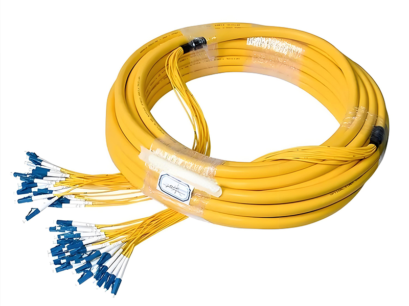
The core of any fiber optic communication system is the optical fiber itself—a thin, flexible strand of glass or plastic designed to transmit light signals over long distances. A typical optical fiber consists of three main components: the core, cladding, and coating. The core is the central part through which light travels, while the cladding surrounds the core and has a lower refractive index, enabling total internal reflection that keeps light within the core.Fiber optic cable.
Optical fibers are classified based on their structure and mode of operation. Single-mode fibers (SMF) have a very small core diameter (typically 8-10 μm) and allow only one mode of light to propagate, making them ideal for long-distance communication with minimal signal dispersion. Multimode fibers (MMF), with larger cores (50-62.5 μm), support multiple propagation modes and are commonly used for shorter distances, such as in local area networks (LANs).
To protect the delicate fiber and facilitate installation, optical fibers are assembled into fiber optic cables. These cables include additional layers for mechanical strength, moisture protection, and resistance to environmental factors. Different cable designs exist for various applications, including loose-tube cables for outdoor use, tight-buffered cables for indoor environments, and ribbon cables for high-density installations.
The performance of optical fibers is characterized by several key parameters, including attenuation (signal loss), dispersion (signal spreading), bandwidth, and numerical aperture (light-gathering ability). Attenuation in modern fibers can be as low as 0.2 dB/km at wavelengths around 1550 nm, allowing for transmission over hundreds of kilometers without amplification.
Advances in fiber manufacturing have led to specialized fibers such as dispersion-shifted fibers (DSF), non-zero dispersion-shifted fibers (NZDSF), and photonic crystal fibers (PCF), each optimized for specific fiber optic applications. These innovations have significantly improved the performance and versatility of fiber optic communication systems.
Fiber Optic Cable Types Comparison
| Cable Type | Core Diameter | Typical Attenuation | Max Distance | Common Applications |
|---|---|---|---|---|
| Single-Mode (SMF) | 8-10 μm | 0.2-0.4 dB/km | 10-100+ km | Long-haul, backbone networks |
| Multimode (OM1) | 62.5 μm | 3.5-4.0 dB/km | 200-300 m | Legacy LANs |
| Multimode (OM3) | 50 μm | 2.2-2.8 dB/km | 300-550 m | High-speed LANs, data centers |
| Multimode (OM5) | 50 μm | 2.0-2.5 dB/km | 300-550 m | WDM over multimode, data centers |
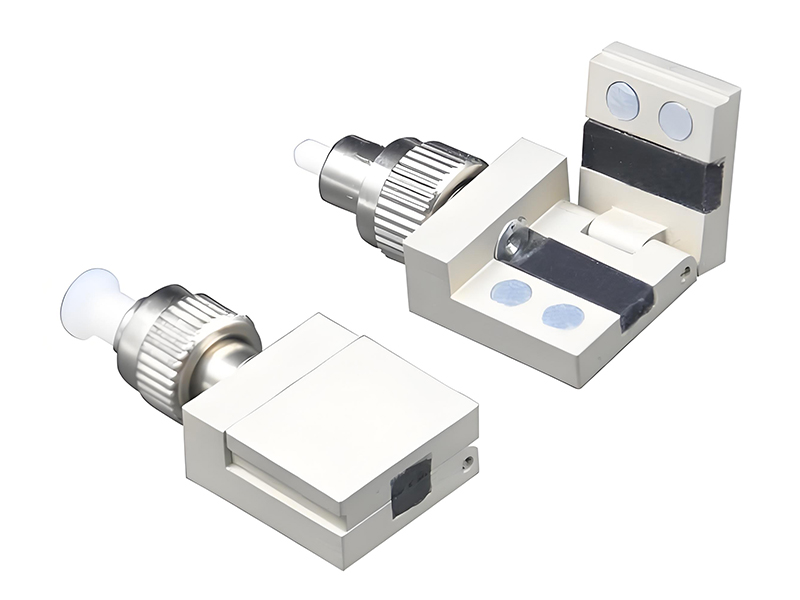
Passive components are essential elements in fiber optic networks—supporting critical applications such as fiber-optic pressure sensors—that manipulate light signals without converting them to electrical signals or requiring an external power source. These components play critical roles in routing, splitting, combining, and filtering optical signals as they traverse the network.
Fiber optic connectors are perhaps the most commonly recognized passive components, enabling detachable connections between fibers and equipment. Key connector types include LC, SC, ST, and MPO/MTP, each with specific designs optimized for different applications. Connector performance is measured by insertion loss (typically less than 0.5 dB) and return loss (ideally greater than 40 dB).
Fiber couplers and splitters distribute optical signals between multiple fibers. Couplers can combine signals from multiple inputs into a single output or split a single input into multiple outputs, with varying splitting ratios (e.g., 50/50, 90/10). Splitters are a type of coupler designed specifically for dividing a signal among multiple outputs, essential for passive optical networks (PONs).
Optical attenuators reduce the power of a light signal to prevent overload in receivers, available as fixed or variable devices. Circulators and isolators control the direction of light propagation, with isolators allowing light to travel in only one direction to protect sensitive components like lasers from back reflections.
Other important passive components include filters for selecting specific wavelengths, gratings for wavelength management, and attenuators for power control. The performance of these components directly impacts the overall efficiency and reliability of fiber optic systems, making their proper selection and installation crucial for network performance.
Connectors & Adapters
Enable detachable connections between fibers and equipment with minimal signal loss, available in various form factors for different applications.
Splitters & Couplers
Distribute or combine optical signals, essential for creating network branches and enabling point-to-multipoint communication architectures.
Isolators & Circulators
Control light direction to protect sensitive components from back reflections and enable complex signal routing in advanced systems.
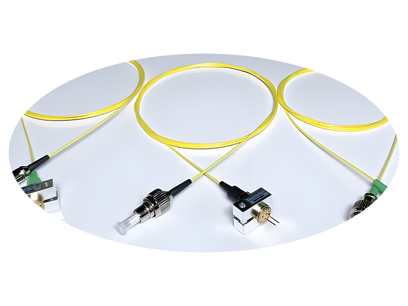
Active components in fiber optic communication systems are devices that require an external power source to operate and typically convert between electrical and optical signals or amplify optical signals directly—though fiber optic technology also finds whimsical, decorative application in items like the fiber optic christmas tree, beyond its core use in communication. These components form the "active" elements that generate, detect, and boost optical signals in a network.
Lasers and light-emitting diodes (LEDs) serve as optical transmitters, converting electrical signals into light signals. Lasers, including distributed feedback (DFB) lasers and vertical-cavity surface-emitting lasers (VCSELs), provide coherent, narrow-spectrum light ideal for high-speed, long-distance transmission. LEDs offer broader spectrum light at lower cost, suitable for shorter-distance, lower-bandwidth applications.
Photodetectors perform the reverse function, converting optical signals back into electrical signals at the receiver end. Common types include PIN photodiodes and avalanche photodiodes (APDs), with APDs providing internal gain for improved sensitivity in low-light conditions. The performance of photodetectors is characterized by responsivity, bandwidth, and noise characteristics.
Optical amplifiers are critical for extending transmission distances by amplifying optical signals directly without converting them to electrical signals. Erbium-doped fiber amplifiers (EDFAs) are widely used in long-haul systems, operating in the 1550 nm wavelength window with high gain and low noise. Other amplifier types include semiconductor optical amplifiers (SOAs) and Raman amplifiers, each with specific advantages for different network scenarios.
Modern fiber optic systems also utilize advanced active components like modulators for encoding data onto light signals, tunable lasers for flexible wavelength management, and wavelength converters for signal processing in complex networks. These components continue to evolve, enabling higher data rates and more efficient network architectures.
Active Components Performance Comparison
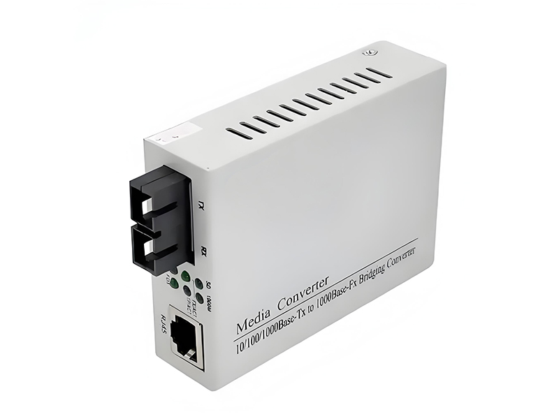
Optical transceivers and modules integrate active components into compact, standardized packages that enable data transmission over fiber optic cable internet networks. These devices serve as the interface between electrical equipment (such as switches, routers, and servers) and optical fiber networks, converting electrical signals to optical signals for transmission and vice versa for reception.
Modern transceivers follow industry standards that define form factors, electrical interfaces, and performance characteristics, ensuring interoperability between different manufacturers. Common form factors include Small Form-factor Pluggable (SFP) and SFP+, Quad Small Form-factor Pluggable (QSFP) and QSFP+, CFP, and XFP modules, each designed for specific data rates and applications.
SFP transceivers are widely used in enterprise networks, supporting data rates from 100 Mbps to 10 Gbps over various distances. SFP+ modules extend this to 10 Gbps with lower power consumption. For higher data rates, QSFP modules support 40 Gbps (using four 10 Gbps lanes) and QSFP28 modules support 100 Gbps (using four 25 Gbps lanes), with emerging QSFP-DD and OSFP form factors targeting 400 Gbps and 800 Gbps.
Optical transceivers are classified based on their transmission distance and wavelength. Short-reach transceivers (SR) typically use multimode fiber and VCSEL lasers for distances up to 550 m. Long-reach (LR) and extended-reach (ER) transceivers use single-mode fiber and DFB lasers, supporting distances up to 10 km and 40 km respectively. For very long distances, ZR (100 km) and DWDM transceivers enable communication over hundreds of kilometers.
The development of fiber optic transceivers has kept pace with the growing demand for higher bandwidth, with advancements in modulation techniques enabling higher data rates over existing fiber infrastructure. Modern coherent transceivers, incorporating advanced digital signal processing (DSP), can achieve terabit per second data rates, making them essential components in next-generation fiber optic networks.
Common Transceiver Form Factors
- SFP/SFP+: 1-10 Gbps, hot-pluggable, compact design
- QSFP/QSFP28: 40-100 Gbps, high-density applications
- CFP/CFP2: 100-400 Gbps, large form factor for high performance
- XFP: 10 Gbps, designed for long-haul applications
- OSFP/QSFP-DD: 400-800 Gbps, next-generation high-speed interfaces
Transceiver Distance Classifications
- SR (Short Reach): Up to 550m, multimode fiber, VCSEL technology
- LR (Long Reach): Up to 10km, single-mode fiber, DFB lasers
- ER (Extended Reach): Up to 40km, single-mode fiber
- ZR (Zetta Reach): Up to 80-120km, for metro and regional networks
- DWDM: Up to 1000+km with amplification, wavelength-specific
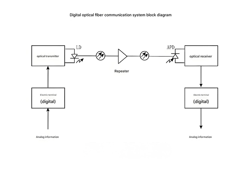
Fiber optic communication systems, which rely on standardized fiber optic color code for efficient cable management and identification, can be categorized as either analog or digital based on how information is encoded onto the optical carrier signal. Each approach has distinct characteristics, advantages, and applications in modern communication networks.
Digital fiber optic systems encode information as discrete binary values (0s and 1s) represented by the presence or absence of light pulses. This approach offers several advantages, including better noise immunity, easier signal regeneration, and compatibility with digital data processing and storage systems. Digital systems typically use intensity modulation with direct detection (IM/DD), where the light intensity is varied to represent digital symbols.
In digital systems, the data rate is a key parameter, measured in bits per second (bps). Modern digital fiber optic systems can achieve data rates from hundreds of megabits per second (Mbps) to several terabits per second (Tbps) using advanced modulation formats and multiplexing techniques. Common digital encoding schemes include non-return-to-zero (NRZ) and return-to-zero (RZ) coding, with more complex formats like pulse amplitude modulation (PAM) and quadrature amplitude modulation (QAM) enabling higher spectral efficiency.
Analog fiber optic systems transmit information by varying a continuous parameter of the optical signal, such as intensity, frequency, or phase, in direct proportion to the input signal. These systems are often used for applications like cable television (CATV) distribution, video surveillance, and sensor networks where the original signal is analog. Analog systems require careful design to manage noise, distortion, and dynamic range, typically specified by parameters like signal-to-noise ratio (SNR) and composite second-order (CSO) distortion.
While digital systems dominate most modern communication infrastructure due to their robustness and compatibility with digital data, analog fiber optic systems remain important for specific applications. Hybrid systems that combine analog and digital transmission over the same fiber are also common, particularly in access networks where video (analog or digitally modulated) and data services are delivered simultaneously to subscribers.
Analog vs. Digital Fiber Optic Systems
| Characteristic | Analog Systems | Digital Systems |
|---|---|---|
| Signal Representation | Continuous variation of optical parameters | Discrete binary states (0s and 1s) |
| Noise Immunity | Susceptible to noise accumulation | High, with regeneration capability |
| Bandwidth Efficiency | Higher for simple signals | Lower for equivalent information |
| Error Correction | Limited capability | Robust with error correction codes |
| Typical Applications | CATV, video surveillance, sensors | Telecommunications, data networks, internet |
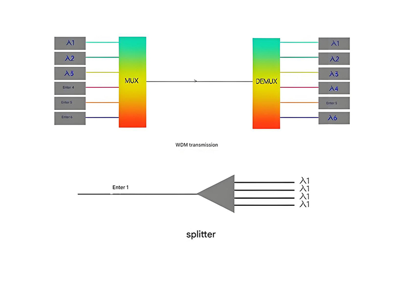
Wavelength Division Multiplexing (WDM) is a revolutionary technology that has transformed fiber optic communication by enabling multiple optical signals to be transmitted simultaneously over a single fiber, each at a different wavelength. This approach multiplies the capacity of fiber optic cables exponentially, making it possible to transmit terabits of data over existing infrastructure.
In a WDM system, multiple optical transmitters operating at different wavelengths (colors) are combined using a multiplexer and launched into a single fiber—typically high-performance fiber optic cables engineered for low signal attenuation and high bandwidth, which are critical for preserving wavelength integrity during transmission. At the receiving end, a demultiplexer separates the signals by wavelength, directing each to its corresponding receiver. This allows for independent data streams to share the same physical medium without interference.
WDM systems are generally categorized as Coarse WDM (CWDM) and Dense WDM (DWDM). CWDM typically uses wavelengths spaced 20 nm apart in the 1310-1625 nm range, supporting 8-16 channels with lower cost components. DWDM systems use much closer wavelength spacing (typically 0.8 nm or less in the 1550 nm window), enabling 40-160 or more channels and much higher overall capacity.
The 1550 nm wavelength window is particularly important for DWDM systems due to its low attenuation in optical fiber and the availability of erbium-doped fiber amplifiers (EDFAs) that can amplify multiple wavelengths simultaneously. This allows DWDM signals to be amplified without demultiplexing, enabling long-haul transmission over thousands of kilometers with periodic amplification.
Advanced WDM techniques include WDM-PON for access networks, ROADMs (Reconfigurable Optical Add-Drop Multiplexers) for flexible network configuration, and ultra-dense WDM with wavelength spacing as small as 12.5 GHz. These innovations continue to push the capacity limits of fiber optic networks, supporting the ever-increasing demand for bandwidth in modern communication systems.
WDM System Components
Optical Multiplexers
Combine multiple optical signals at different wavelengths onto a single fiber
Optical Demultiplexers
Separate combined WDM signals into individual wavelengths at the receiver
Optical Amplifiers
Amplify multiple wavelengths simultaneously without converting to electrical signals
ROADMs
Reconfigurable devices that add, drop, or route specific wavelengths in the network
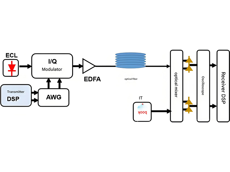
Coherent optical communication represents a significant advancement in fiber optic technology, enabling unprecedented data rates and transmission distances by leveraging the full properties of light waves—amplitude, phase, frequency, and polarization. Unlike traditional intensity-modulated systems, coherent systems use both amplitude and phase modulation, combined with advanced digital signal processing (DSP), to encode more information per symbol.
The kentucky fiber optic network dispute, which centers on issues like fiber infrastructure expansion and performance requirements for regional connectivity, underscores the importance of advanced optical technologies— including coherent detection. The key principle behind coherent detection is the use of a local oscillator (LO) laser at the receiver that is phase-locked to the incoming signal. This allows for the detection of both amplitude and phase information, whereas direct detection systems only measure intensity. By utilizing phase modulation formats like quadrature phase-shift keying (QPSK) and higher-order quadrature amplitude modulation (QAM), coherent systems can achieve much higher spectral efficiency, directly addressing the performance demands at the heart of the Kentucky dispute.
Modern coherent fiber optic systems typically employ polarization-division multiplexing (PDM), transmitting two independent data streams on orthogonal polarizations of light. This effectively doubles the data rate without increasing the symbol rate or requiring additional bandwidth. When combined with 16-QAM modulation, PDM enables data rates of 100 Gbps per wavelength, with 64-QAM and higher formats pushing this to 200 Gbps and beyond.
Digital signal processing (DSP) is a critical enabling technology for coherent systems, performing functions such as equalization to compensate for fiber impairments like chromatic dispersion and polarization mode dispersion (PMD), carrier phase recovery, and polarization demultiplexing. These advanced signal processing techniques allow coherent systems to achieve performance levels that were previously unattainable with traditional fiber optic technologies.
Coherent technology has become the standard for long-haul and ultra-long-haul fiber optic transmission systems, enabling transoceanic cables and continental backbones to carry terabits of data. Recent developments have extended coherent technology to shorter-reach applications like metro networks and data center interconnects, making it a versatile solution across the entire communications infrastructure.
Coherent Modulation Formats Comparison

The Optical Transport Network (OTN) is a set of standards and protocols defined by the ITU-T that specifies how to transport client signals over fiber optic networks—including specialized variants like epb fiber optics (which offer enhanced signal integrity and lower attenuation to support OTN’s high reliability demands)—efficiently, reliably, and scalably. OTN provides a robust framework for managing the complexity of modern optical networks, supporting multiple services and data rates while offering sophisticated monitoring and protection capabilities that align with the performance characteristics of epb fiber optics.
At its core, OTN defines a hierarchical frame structure that encapsulates various client signals—including SDH/SONET, Ethernet, Fibre Channel, and video signals—into optical data units (ODUs) and optical transport units (OTUs). This encapsulation provides a uniform way to transport diverse services over fiber optic infrastructure, enabling interoperability between different network elements and vendors.
OTN technology includes several key components and functions. Optical channel data units (ODUs) provide path layer functionality, including error monitoring via bit error rate (BER) measurements. Optical transport units (OTUs) handle section layer functions, including frame alignment and error correction using forward error correction (FEC). The FEC capability in OTN significantly improves system performance, extending reach and allowing for higher data rates.
One of the primary advantages of OTN is its robust network management and monitoring capabilities through the use of overhead bytes in the frame structure. These overhead bytes enable end-to-end performance monitoring, fault localization, and network management, making OTN networks highly reliable and easier to maintain. OTN also supports various protection schemes, including linear protection and ring protection, ensuring high availability of services.
Modern OTN implementations, often referred to as Flexible OTN or FlexO, support higher data rates (up to 400 Gbps and beyond) and more flexible bandwidth allocation, making them suitable for next-generation fiber optic networks. OTN has become the standard for core and metro transport networks, providing the foundation for scalable, reliable, and efficient delivery of the ever-increasing volume of data in modern communication systems.
OTN Protocol Layers
Optical Channel Transport Unit (OTU)
Section layer - Frame alignment, FEC, section monitoring
Optical Channel Data Unit (ODU)
Path layer - Path monitoring, tandem connection monitoring
Optical Channel Payload Unit (OPU)
Payload adaptation - Client signal encapsulation
Client Signals: Ethernet, SDH/SONET, Fibre Channel, Video, etc.
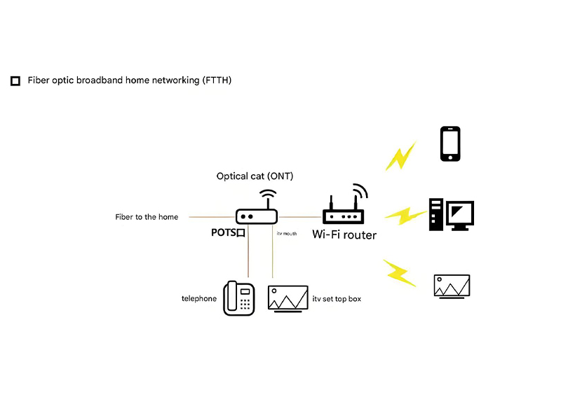
Optical access networks bring fiber optic technology directly to homes, businesses, and other end-user locations, providing high-bandwidth connectivity that supports modern applications like streaming video, cloud services, and high-speed internet access. These networks represent the "last mile" of the communication infrastructure— a segment where fiber optic drone plays a critical role in maintenance (e.g., inspecting fiber lines for damage) and emergency support (e.g., restoring temporary connectivity if ground access is disrupted)—connecting the core network to individual subscribers reliably.
The most common optical access network architecture is the Passive Optical Network (PON), which uses passive components to split and distribute signals from a central office to multiple subscribers. PON systems typically consist of an Optical Line Terminal (OLT) at the service provider's central office, Optical Network Units (ONUs) or Optical Network Terminals (ONTs) at the subscriber premises, and a passive optical splitter in the field that divides the signal among multiple users.
Several PON standards have been developed to meet different bandwidth requirements. GPON (Gigabit PON) and EPON (Ethernet PON) are widely deployed, offering gigabit-class speeds. More recent standards like XGS-PON and 10G EPON provide symmetric 10 Gbps speeds, while NG-PON2 (Next-Generation PON Stage 2) supports even higher speeds (up to 40 Gbps) using wavelength division multiplexing (WDM) to provide dedicated wavelengths to individual subscribers.
Fiber-to-the-home (FTTH) networks bring fiber all the way to residential premises, offering the highest performance. Other deployment scenarios include Fiber-to-the-Building (FTTB), Fiber-to-the-Curb (FTTC), and Fiber-to-the-Cabinet (FTTCab), where fiber is brought close to the subscriber with a copper connection for the final short distance. Each approach balances performance, cost, and deployment complexity based on specific requirements.
The deployment of fiber optic access networks is driven by the increasing demand for bandwidth from applications like 4K/8K video streaming, virtual reality, and the Internet of Things (IoT). As these networks continue to evolve, technologies like wavelength-aware networks and software-defined access networks are emerging to provide even greater flexibility, capacity, and intelligence, ensuring that optical access networks can meet the needs of future communication services.
PON Network Architecture
OLT
Optical Line Terminal
Central Office
Splitter
Passive Optical Splitter
Distribution Point
ONU/ONT
Optical Network Unit
Subscriber Premises
