For decades, the fiber optic cable has revolutionized telecommunications, enabling the high-speed data transfer that powers our modern digital world. This guide explores the fundamental principles, characteristics, types, and manufacturing processes behind these remarkable transmission mediums.Optical Transceiver.
Principles of Light Guidance in Optical Fibers
The core functionality of a fiber optic cable relies on the principle of total internal reflection, a phenomenon that allows light to travel through the fiber with minimal loss. This principle was first demonstrated by Daniel Colladon and Jacques Babinet in the 1840s, laying the groundwork for modern fiber optic technology— a foundation that fiber optic training (training designed to equip technicians with the knowledge to work with fiber optics) builds on to teach practical skills. Fiber optic training starts with mastering concepts like total internal reflection and the historical context of fiber development, ensuring learners grasp the "why" behind fiber design before moving to hands-on tasks like cable installation or signal testing.
An optical fiber consists of two main components: the core and the cladding. The core is the central part through which light travels, while the cladding surrounds the core. The key to total internal reflection is that the core has a higher refractive index than the cladding.
Total Internal Reflection Explained
When light travels from a medium with a higher refractive index to one with a lower refractive index, it bends away from the normal line. As the angle of incidence increases, the refracted angle approaches 90 degrees. Beyond the critical angle, no refraction occurs—all light is reflected back into the higher refractive index medium.
This reflection mechanism allows light signals to propagate through the fiber optic cable over long distances with minimal attenuation. The light essentially "bounces" off the boundary between the core and cladding, maintaining its intensity as it travels.
Modern optical fibers use ultra-pure glass or plastic materials to minimize absorption and scattering losses. The core diameter can range from a few micrometers to hundreds of micrometers, depending on the application and type of fiber.
In addition to total internal reflection, fiber optic cable design considers mode theory—the number of possible paths (modes) that light can take through the fiber. This classification forms the basis for distinguishing between single-mode and multimode fibers, each with distinct characteristics and applications.
Light Propagation in Optical Fiber
Core (n₁)
Central region with higher refractive index
Cladding (n₂)
Outer layer with lower refractive index (n₂ < n₁)
Light Path
Follows total internal reflection at core-cladding boundary
Critical Angle Calculation
θc = sin-1(n₂/n₁)
For typical fibers: θc ≈ 76.7°
Transmission Characteristics of Optical Fibers
The performance of a fiber optic cable is determined by several key transmission characteristics that dictate how effectively it can carry light signals over distance. These characteristics include attenuation, dispersion, bandwidth, and signal-to-noise ratio—with attenuation being particularly relevant for applications like 2 ft fiber optic christmas trees (compact decorative trees where fiber optics transmit light to create festive glowing effects). In these small-scale decorations, the same attenuation principle that governs industrial cables ensures light travels the short 2 ft distance without significant loss, keeping the tree’s light output bright and consistent across all fiber tips.
Attenuation
Attenuation refers to the loss of signal strength as light travels through the fiber optic cable. It is typically measured in decibels per kilometer (dB/km). Lower attenuation values indicate better performance, as signals can travel longer distances without amplification.
The main causes of attenuation include absorption (where light energy is absorbed by the fiber material), scattering (where light is scattered by impurities or density fluctuations), and bending losses (both macro-bending and micro-bending).
Dispersion
Dispersion is the phenomenon where different components of a light signal travel at different speeds, causing the signal to spread out over distance. This spreading limits the bandwidth and transmission distance of a fiber optic cable.
There are several types of dispersion: material dispersion (caused by wavelength-dependent refractive index), waveguide dispersion (resulting from the fiber's structure), and modal dispersion (occurring in multimode fibers due to different path lengths of various modes).
Bandwidth
Bandwidth refers to the information-carrying capacity of a fiber optic cable, typically measured in megahertz-kilometers (MHz·km) or gigahertz-kilometers (GHz·km). It represents the product of the maximum data rate and the maximum transmission distance without significant signal degradation.
Single-mode fibers offer much higher bandwidth than multimode fibers due to their ability to eliminate modal dispersion, making them ideal for long-haul, high-data-rate applications.
Temperature and Environmental Effects
The performance of a fiber optic cable can be affected by temperature variations, humidity, and mechanical stress. Modern cable designs incorporate protective layers and materials to minimize these effects, ensuring reliable operation across a wide range of environmental conditions.
Fiber Optic Transmission Characteristics
Attenuation vs. Wavelength
Optical fibers exhibit minimum attenuation in specific wavelength windows: 850nm, 1310nm, and 1550nm, which are the primary operating wavelengths for fiber optic systems.
Typical Performance Metrics
Signal dispersion visualization in multimode vs single-mode fiber optic cable
Introduction to Common Optical Fibers
Optical fibers come in various types, each designed for specific applications based on their structure, material, and performance characteristics. The fiber optic cable market offers a range of options, including fiber optic snowman, to meet diverse transmission requirements, from short-distance data centers to long-haul telecommunications networks.
Single-Mode Fibers (SMF)
Single-mode fibers have a very small core diameter (typically 8-10 μm) that allows only one mode of light to propagate. This eliminates modal dispersion, enabling them to transmit signals over much longer distances with higher bandwidth compared to multimode fibers.
The most common type is G.652, often referred to as standard single-mode fiber, which operates optimally at 1310nm and 1550nm wavelengths. Other variants include G.655 (non-zero dispersion-shifted fiber) designed for wavelength-division multiplexing (WDM) systems.
Applications for single-mode fiber optic cable include long-haul telecommunications, submarine communications, and high-speed backbone networks.
Multimode Fibers (MMF)
Multimode fibers have a larger core diameter (typically 50 μm or 62.5 μm) that allows multiple modes of light to propagate simultaneously. While they offer higher light-gathering capacity and easier connectorization, they suffer from modal dispersion, limiting their bandwidth and transmission distance.
Common multimode fibers include OM1 (62.5/125 μm), OM2 (50/125 μm), OM3, and OM4 (laser-optimized 50/125 μm). The "OM" designations indicate increasing bandwidth capabilities, with OM4 supporting 100Gbps Ethernet over distances up to 150 meters.
Multimode fiber optic cable is commonly used in local area networks (LANs), data centers, and short-distance communication links.
Specialty Fibers
Beyond standard single-mode and multimode fibers, there are numerous specialty fibers designed for specific applications:
- Polarization-maintaining fibers preserve the polarization state of light, used in sensing and coherent communication systems
- Erbium-doped fiber amplifiers (EDFAs) amplify optical signals directly without converting to electrical signals
- Photonic crystal fibers with air holes in the cladding, offering unique dispersion and nonlinear properties
- Plastic optical fibers (POF) using plastic materials, offering low cost and easy handling for short-distance applications
Fiber Optic Cable Types Comparison
| Characteristic | Single-Mode | Multimode |
|---|---|---|
| Core Diameter | 8-10 μm | 50 or 62.5 μm |
| Cladding Diameter | 125 μm | 125 μm |
| Light Sources | Laser diodes | LEDs, VCSELs |
| Maximum Distance | Tens of kilometers | Up to 2 km |
| Bandwidth | Very high (>100 GHz·km) | Moderate (200-2000 MHz·km) |
| Cost | Higher | Lower |
Fiber Optic Cable Construction
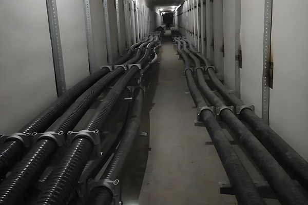
A typical fiber optic cable consists of optical fibers, buffer tubes for protection, strength members for tensile strength, and an outer jacket for environmental protection.
Design and Manufacturing of Fiber Optic Cables
The design and manufacturing of a fiber optic cable involve precise engineering and sophisticated processes for fiber optic splitter, ensuring optimal performance, reliability, and durability. From raw material selection to final testing, each step requires careful attention to detail.
Fiber Design Considerations
The design process begins with defining the fiber optic cable's intended application, which dictates critical parameters such as:
- Core and cladding dimensions and refractive index profiles
- Operating wavelength range
- Required bandwidth and transmission distance
- Environmental conditions (temperature, humidity, chemical exposure)
- Mechanical requirements (tensile strength, flexibility, crush resistance)
- Installation environment (underground, aerial, submarine, indoor)
Preform Manufacturing
The first step in producing optical fiber is creating a preform—a large-diameter glass rod with the same refractive index profile as the final fiber, but on a much larger scale. Preforms are typically manufactured using one of several techniques:
Modified Chemical Vapor Deposition (MCVD)
In MCVD, a mixture of gases (including silicon tetrachloride and germanium tetrachloride) is passed through a rotating silica tube. A heat source (oxyhydrogen torch) traverses the tube, causing the gases to react and deposit silica-based glass layers on the inner wall.
Other methods include Outside Vapor Deposition (OVD), Vapor Axial Deposition (VAD), and Plasma Chemical Vapor Deposition (PCVD), each with its own advantages in terms of efficiency, purity, and fiber characteristics.
Fiber Drawing
The preform is heated in a drawing tower to convert it into a thin optical fiber. The preform is fed into a furnace (typically carbon or graphite) operating at approximately 2000°C, where the tip softens and forms a molten droplet. As the droplet falls, it solidifies into a continuous fiber strand.
During drawing, the fiber diameter is carefully monitored and controlled (typically to 125 μm for the cladding) using laser micrometers and feedback systems. Drawing speeds can range from 10 to 20 meters per second, producing kilometers of fiber from a single preform.
Cabling Process
After drawing, individual optical fibers are assembled into a fiber optic cable through several processes:
- Buffering: Applying a protective coating (typically acrylate) to the fiber to protect against mechanical damage and microbending
- Stranding: Grouping buffered fibers into bundles, often around a central strength member
- Jacketing: Applying an outer protective layer (PVC, polyethylene, or other materials) based on environmental requirements
- Armoring: Adding metal or non-metallic strength members for additional protection in harsh environments Electronic shelf labels.
Testing and Quality Control
Rigorous testing is performed at every stage of fiber optic cable manufacturing to ensure performance meets specifications. Tests include:
- Attenuation measurement across operating wavelengths
- Bandwidth and dispersion testing
- Mechanical testing (tensile strength, crush resistance, bend performance)
- Environmental testing (temperature cycling, humidity resistance)
- Optical time-domain reflectometry (OTDR) to detect defects or irregularities Related Hydraulic Spare Parts.
Fiber Optic Cable Manufacturing Process
Preform Manufacturing
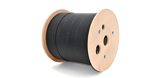
Creating high-purity glass preforms with precise refractive index profiles
Fiber Drawing
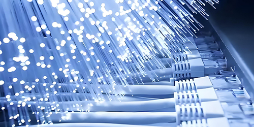
Pulling ultra-thin fiber from the preform in a controlled heating process
Coating and Buffering
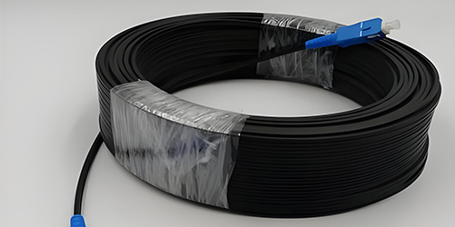
Applying protective layers to enhance mechanical strength and performance
Cable Assembly
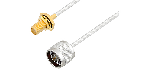
Assembling fibers into final cable configuration with strength members and outer jacket
Quality Control Parameters
Key Manufacturing Tolerances
The Future of Fiber Optic Technology
As demand for higher bandwidth and faster data transmission continues to grow, the fiber optic cable remains the foundation of our global communication infrastructure. Advancements in materials science and manufacturing techniques promise even higher performance, lower costs, and new applications for this remarkable technology. Related Lithium ion battery.